Site and Site Configuration
Site
A site in our EMS system represents an entity such as a factory, business office, or apartment building. Typically, a site is defined by a single connection to the electrical grid. Each site operates as an independent entity, managing energy flow, monitoring devices, and optimizing operations for its designated grid connection.
Site Configuration
The site configuration defines the topology of the site that requires optimization. Without a proper configuration, the system cannot generate accurate optimization recommendations.
This section provides an overview of the key components of a typical site configuration, which consists of two main elements: the collector list and the device list.
Collector List
The collector list defines the relevant collectors within the electrical grid being optimized. Future updates will support multiple collectors with different commodities (e.g., electricity, gas, hot water), but currently, only electricity collectors are supported.
Collectors are organized in a parent-child hierarchy, where different attributes may be required depending on their role.
Collector
The collector schema applies to both parent (main) and child (sub) collectors. Child collectors can additionally specify phase and phase_permutations fields.
{
  "name": "main_collector",
  "children": [
    null
  ],
  "line_current": 400,
  "line_voltage": 400,
  "phase_voltage": 230,
  "commodity": "electricity",
  "nb_of_phases": 0
}
Collector
- array
- null
- Array [
- ]
- 0-item-properties
- null
- integer
- null
- integer
- null
children object
The children of this collector. This is used to create a tree structure.
phase_permutations object
If the phase naming conventions (L1, L2, L3) are not consistent between parent and child, specify the phase mapping between them.
The line current in Ampere.
line_voltage object
The line voltage is in Volt. You should provider either line_voltage or phase_voltage (or both)
phase_voltage object
The phase voltage is in Volt. You should provider either line_voltage or phase_voltage (or both)
electricitySpecifies whether the collector is single-phase (1P) or three-phase (3P).
3PSetting a different line voltage in a child collector allows the inclusion of transformers, but transformer losses are not accounted for.
Device List
3-Phase Charging Station
{
  "name": "LR34_001",
  "collector": "main_collector",
  "type": "charging_pole_3phase",
  "line_current": 32
}
AC Charging Pole (3-Phase)
The name of the device itself. This value will be used as the asset ID in the rest of the API.
The name of the collector to which this device is connected.
charging_pole_3phasecharging_pole_3phaseThe line current in Ampere.
Defines how charging pole pins map to the collectors' phases. For more information see the 'Key Concepts - Site configuration' section in the documentation.
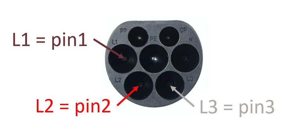
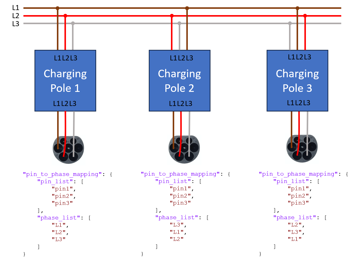
In order to balance power over the phases when lots of single phase charging sessions are ongoing, it is common practice to rotate the phases of the charging stations. In order to make sure that the optimization software calculates the power on each phase correctly, it is important that phase mapping of each individual charging pole is correctly configured. The figure below shows the pinning of a CCS type 2 connector, having 3 pins connecting the phases of the grid to the car. On the connector they are referred to as L1, L2 and L3 but that does not mean that they are actually connected to the L1, L2 and L3 phases of the grid. In the terminology below, pins refer to the pins of the connector.
The figure below shows how rotating phases should be configured in the pin_to_phase_mapping field of a three-phase charging pole. The pin_list refers to the physical pins on the connector, the phase_list refers to the phases of the grid.
Single-Phase Charging
Single-phase charging is handled using the same charging_pole_3phase device type. To configure a charging pole for single-phase operation, set up the pin_to_phase_mapping with only the pin that will be used. The number of phases used during a charging session is determined by the usedChargingPins field in the transaction payload.
The charging pole inherits the voltage from the collector it is connected to.
3-Phase Forecasted Series
A forecasted series can be added for any non-controllable three-phase device with predictable energy patterns.
We support photovoltaic (PV) and uncontrollable load (UCL) forecasting.
{
  "name": "LR34_001",
  "collector": "main_collector",
  "type": "forecasted_series_3phase",
  "line_current": 32,
  "should_be_aggregated": false
}
Forecasted 3-Phase Device
The name of the device itself. This value will be used as the asset ID in the rest of the API.
The name of the collector to which this device is connected.
forecasted_series_3phaseforecasted_series_3phaseThe line current in Ampere.
Defines the type of forecast to be used for this device.
falseThis document provides a structured guide to configuring sites within the EMS system, ensuring accurate energy optimization for different setups.